best service ,best view
contact us email : 718642093@qq.com
Better service ,Better Design
contact us 718642093@qq.com

Method and system for welding railroad rails-5
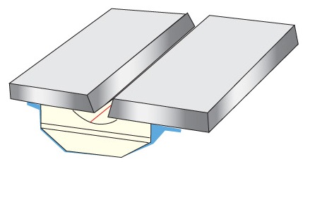
In accordance with still another aspect of the invention, the intersection or joint between the end of a rail and the backing plate is processed to provide a fillet weld as the angled torch is moved along this joint. The fillet weld is between the thick heavy end of a rail and the thin backing plate. This fillet welding aspect of the present invention can be used in various other joints where a heavy piece of metal is connected to a thin metal plate. In the fillet weld in the junction between the backing plate and the end of a rail, it is desirable to have nearly 100% penetration to produce a smooth contour on the back side of the weld. This smooth contour crucial to proper appearance of the root weld. In this fillet area of the root pass, an arc blow through is wanted to control the penetration of molten metal between the insert and the rail. If inadequate penetration occurs, the base metal at the fillet weld joint is not be completely consumed. This leads to a cold laps or notches on the backside of the weld. If there is too much penetration at this weld junction, a sharp re-entry angle may be formed from the backside of the weld. In addition, the metal overlaps the parent material of the rails forming a notch. These are disadvantages overcome by the present invention whereby a controlled arc blow through is automatically accomplished periodically along the fillet weld. The automatic control allows a weld motion controller, such as in a robot mechanism, guarantees periodic blow throughs in the fillet weld, at least in successive longitudinal branches of the weld pattern. By sensing and controlling the number and position of the periodic blow throughs an ideal weld in the fillet area of the root pass is obtained. Assurance of periodic arc blow throughs in the fillet joint is the objective of this aspect of the invention. When moving the torch along the selected path, at the intersection between the swinging action and the longitudinal movement, there is a decision point. These decision points extend along the fillet joint. When the arc reaches one of these decision points, it is determined whether there has been arc blow through as sensed by a drop in arc current. If there is a blow through, this is recorded. If there is no blow through at a first longitudinal branch in the section of the fillet joint, the torch continues to cross the gap and can come back to the next longitudinal branch on the same side of the gap. At this next longitudinal branch along the junction between the backing plates and edge of the rail a blow through must occur. In other words, there must be a blow through in accordance with this aspect of the invention at a first or second successive branch constituting the short longitudinal branches of the torch as it moves along the rail. If there is not a natural blow through at the second branch, then the voltage is decreased reducing the foot print of the arc. This causes a sharp penetration of the arc and creates a forced blow through. By having a blow through, forced or unforced, at least one time during each successive longitudinal branches along the fillet between the swinging action of the torch, a fillet joint is created that has nearly 100% penetration. This aspect of the present invention maintains a quality fillet weld in the root pass.
Date: 2023-04-10 hits: 907 Return
Spot welding ( Ceramic Backing) 2023-04-10
Ultrasonic welding( RIHUI Backing) 2023-04-10
Spot welding( RIHUI Ceramic Welding Backing) 2023-04-10