best service ,best view
contact us email : 718642093@qq.com
Better service ,Better Design
contact us 718642093@qq.com

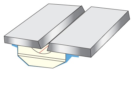
Method and system for welding railroad rails-6
The present invention is performed by standard robotic control or mechanism as used to perform the welding operation in Morlock U.S. Pat. No. 5,773,779 and Morlock U.S. Pat. No. 5,877,468. In accordance with the present invention, there is provided a method of depositing metal from an advancing welding wire carried in a torch to form a root pass of weld metal in the bottom of a gap between first and second metal members, preferably railroad rails, which members have generally flat base elements joined by a metal backing plate extending between the base elements. The method comprises passing welding current between the welding wire in the torch and the metal members from the power supply to create a heat generating welding arc, moving the welding wire in a given direction along a selected path over the backing plate, and sensing an arc blow through of the backing plate by the welding arc. In one embodiment, a sensed blow through causes reversal of the given direction of the welding wire or torch for a short distance of less than about ¼ inch when a blow through has been sensed and then resuming movement of the welding wire or torch in the given direction along the selected path. In this manner, when there is an unwanted blow through of the backing plate, the torch moves back slightly allowing molten metal to fill the blow through hole so the welding process can continue uninterrupted without cutting a kerf in the bottom backing plate. In the present implementation of the invention, there are computer recognized decision points at each change in direction of the selected path between a transverse branch and a short longitudinal branch. When a blow through is sensed, the torch or welding wire is reversed in direction and goes back to the previous decision point. The invention also senses a wanted or forced blow through in the fillet area to assure periodic blow through holes to provide excellent penetration.
Date: 2023-04-10 hits: 863 Return
Spot welding ( Ceramic Backing) 2023-04-10
Ultrasonic welding( RIHUI Backing) 2023-04-10
Spot welding( RIHUI Ceramic Welding Backing) 2023-04-10