best service ,best view
contact us email : 718642093@qq.com
Better service ,Better Design
contact us 718642093@qq.com

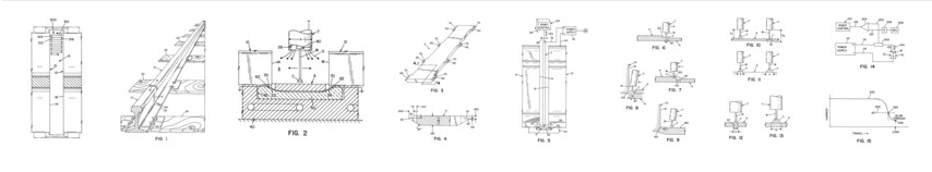
FIG. 1 is a pictorial view of two railroad rails with a gap g to be filled by a robotic controlled arc welding process as disclosed in Morlock U.S. Pat. No. 5,773,779 and Morlock U.S. Pat. No. 5,877,468;
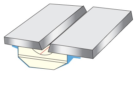
FIG. 2 is an enlarged cross sectional area at the bottom of the gap between the rails showing a torch type used in practicing the present invention and as used in the prior patents by Morlock assigned to the present assignee;
FIG. 3 is a pictorial view of the backing plate used in the preferred embodiment of the present invention;
FIG. 4 is an enlarged cross sectional view taken generally along line 4—4 of FIG. 3;
FIG. 5 is a side view illustrating a welding gap in the robotic control mechanism and power supply used in the preferred embodiment of the present invention to provide the root pass in the gap;
FIG. 6 is a schematic view of the torch carrying the welding wire moving across the backing strip and creating an arc blow through;
FIG. 7 is a view similar to FIG. 6 showing the corrective action taken in accordance with the present invention after a blow through occurs in the backing plate;
FIG. 8 is a schematic cross sectional view at the fillet junction between the backing plate and one of the rails illustrating an arc blow through created in accordance with an aspect of the present invention;
FIG. 9 is a view similar to FIG. 8 showing corrective action of the torch taken after the blow through has occurred;
FIGS. 10-13 are schematic views illustrating the concept of arc blow through and control of the blow through by arc adjustment of the power supply;
FIG. 14 is a schematic wiring diagram illustrating the sensing circuit for sensing an arc blow through and adjusting the robotic control mechanism for taking correction action after a blow through;
FIG. 15 is a graph showing the operating parameters of the control circuit shown in FIG. 14;
FIG. 16 is top plan view of the welding gap above the backing plate showing the selected weld pattern created by the robotic control mechanism in accordance with the present invention;
FIG. 17 is an enlarged view of a portion of the weld pattern shown in FIG. 16 showing aspects of the present invention;
FIG. 18 is view similar to FIG. 17 showing further control aspects of the present invention as the weld torch progresses along the selected pattern;
FIGS. 19-21 are cross sectional views of the fillet area of the root pass showing three penetration conditions, one of which is obtained by using the present invention; and,
FIG. 22 is a composite view showing three fillet conditions between the plate and rail that can be encountered when using the present invention.
Date: 2023-04-10 hits: 850 Return
Spot welding ( Ceramic Backing) 2023-04-10
Ultrasonic welding( RIHUI Backing) 2023-04-10
Spot welding( RIHUI Ceramic Welding Backing) 2023-04-10