best service ,best view
contact us email : 718642093@qq.com
Better service ,Better Design
contact us 718642093@qq.com

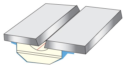
Referring to the drawings wherein the showings are for the purpose of illustrating a preferred embodiment of the invention only, and not for the purpose of limiting same, FIG. 1 shows two spaced railroad rails 10, 12 mounted on railroad ties 20 and provided with a gap g between oppositely facing surfaces 14, 16, respectively. The gap g is provided between the rails for the purposes of joining the rails in the field by using a robotic control mechanism to perform a welding operation as illustrated in Morlock U.S. Pat. No. 5,773,779 and Morlock U.S. Pat. No. 5,877,468. Gap g is above flat base portions 22, 24, which portions are used to support a lower backing plate A, positioned below flat bases 22, 24 to define the root pass area. A root pass is the first layer of molten metal to be deposited by the electric arc welding process in gap g. As shown in FIGS. 2-4, backing plate A is supported in the longitudinally extending recess 42 in copper shoe 40 so that recess extends between rails 10, 12 to receive a ceramic tile or element 50. This element holds lower backing plate A against the lower sides of flat bases 22, 24 of rails 10, 12, respectively. As shown in FIGS. 3 and 4, backing plate A has outwardly protruding end tabs 60and a number of center tabs 62, which number is determined by the length of the gap g. Consumable plate A is supported on ceramic tile or element 50 and is held against edges 22, 24 by notches 70 having the preferred dimensions set forth in FIG. 4. The dimensions of plate A are also provided for a gap g having a width of approximately 1.0 inches. Molten metal of the root pass is deposited on the top of consumable plate A after the plate is assembled as shown in FIGS. 2 and 5. Welding torch T of an electric arc welder is moved in accordance with a robotic control mechanism 100 to follow a desired or selected welding pattern or path during the root pass welding operation. Torch T has a diameter x with a cylindrical housing surrounding wire holder 80 for directing welding wire W toward plate A. An appropriate power supply 110, in practice a constant voltage power supply, directs current flow at lines 112, 114 through welding wire W to plate A to create an electric arc C, which arc creates the heat used to melt advancing wire W to create molten metal that is deposited on plate A. The molten metal melts the plate and creates a root pass joining bottom flat areas 22, 24 preparatory to subsequent upper welding to fill gap g. The distance between holder 80 and plate A is the stick-out ESO, which stick-out determines the resistance of the welding operation as seen by power supply 110. Shielding gas S enters gap g through passage 26, between holder 80 and the outer housing of torch T. As so far described, the root pass welding process is the same procedure being tested by assignee of the present application.
Date: 2023-04-10 hits: 858 Return
Spot welding ( Ceramic Backing) 2023-04-10
Ultrasonic welding( RIHUI Backing) 2023-04-10
Spot welding( RIHUI Ceramic Welding Backing) 2023-04-10