best service ,best view
contact us email : 718642093@qq.com
Better service ,Better Design
contact us 718642093@qq.com

Method and system for welding
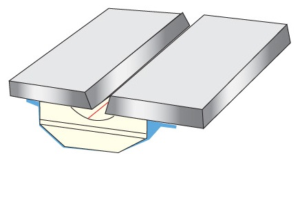
As indicated in FIG. 10, the stick-out D1 between the holder in torch T remains constant during the movement of torch T to form the root pass at fillet edges 140. As shown in the right in FIG. 10, when there is a blow through, hole BT causes the stick-out to be substantially greater as indicated by D2. Consequently, with a greater stick-out in a welding operation using a constant voltage power supply 110, the arc current is reduced during arc blow through. In accordance with the invention, the arc current is sensed. The value of current is used to detect a blow through to take the correction action as illustrated in FIGS. 7 and 9. To cause a forced blow through when needed in the fillet area at the edges 140, the procedure illustrated in FIG. 11 is utilized. As shown on the right, torch T moves along plate A and melts wire W by the heat of arc C. During normal operation in depositing molten metal from wire W onto plate A, the plate A is also consumed by the heat of the arc. As illustrated, arc C has a nominal diameter above plate A. As arc C moves toward the fillet area, it retains its general diameter a. Upon reaching fillet area at edge 140, as will be described later, there may not be an arc blow through, which may be determined by the fillet geometry shown in FIG. 22. To create an ideal fillet joint at edges 140, however, there is a need for a periodic blow through especially in the area of tabs 60, 62. This area is shown at the bottom view in FIG. 22. A blow through is desired at least periodically in the fillet area. To force a blow through, the voltage of power supply 110 is reduced. The reduction of the voltage causes the diameter of arc C to be reduced as shown by diameter b for torch T at the left in FIG. 11. When this occurs, there is a more concentrated arc having a greater arc force and a smaller footprint than the large footprint shown on the right. This creates a forced blow through when required in the fillet area at edge 140. The large footprint of a normal arc is illustrated in FIG. 13, whereas the small footprint of a forced blow through arc is shown in FIG. 12 where the arc caused a blow through hole BT. This concept is used in accordance with the present invention when it is desired to have a forced blow through to control the welding between plate A and the edge 140 along the bottom base of rails 10, 12. An aspect of the invention uses this forced blow through procedure as will be explained later.
More information: http://www.welding-backing.com/
Date: 2023-04-10 hits: 933 Return
Spot welding ( Ceramic Backing) 2023-04-10
Ultrasonic welding( RIHUI Backing) 2023-04-10
Spot welding( RIHUI Ceramic Welding Backing) 2023-04-10