best service ,best view
contact us email : 718642093@qq.com
Better service ,Better Design
contact us 718642093@qq.com

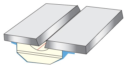
Method and system for welding ceramics
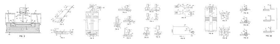
Referring now to FIGS. 16-18, in accordance with the invention, torch T is moved in the selected path 300 shown in FIG. 16. This path includes a series of cycles including transverse branches 310, 312 and connecting longitudinal branches 314 and316. Torch T swings along transverse branch 310 to a position shown in FIG. 8. It then moves longitudinally along fillet edge140, as branch 314. Branch 314 has a short length necessary to cause overlapping of molten metal and is generally only slightly larger than the diameter of the wire being used for forming the root pass. With the wire 1.6 mm in diameter, the branches 314, 316 are about 2-3 mm in length. Thereafter, torch T swings along branch 312 and then moves longitudinally along edge 140 along branch 316. This cycle is repeated to lay a total weld on consumable backing plate A. The selected path 300 is generally rectilinear indicating transverse movement of the torch or orthogonal longitudinal movement of the torch. As shown in FIG. 17, if there is a blow through BT along path 310, torch T reverses direction as indicated by arrow 320 and then resumes its original movement as indicated by arrow 322. If the blow through in branch 310 is at edge 140, as shown in FIG. 8, reversal movement is caused along transverse branch 310, back to branch 316 or back a short distance. This allows closing of the blow through hole BT, as shown in FIG. 9. If the blow through is in branch 310 but spaced from the edge 140, the same thing occurs and the blow through hole BT is filled. As shown in FIG. 18, there are two blow throughs BT. In the first instance, blow through is recorded for this branch and will not be forced on the next 314 branch. In the second instance, blow through has been detected along the 312 branch, thus a reversing motion will take place before resuming forward motion along branch 316. Referring again to FIG. 16, the right angle intersection between branches 310, 312, 314 and 316 are marked with a cross. These crosses are decision points for the software program controlling the root pass welding process. All the decision points, in the current implementation of the invention, are along the fillet edge 140 between backing plate A and rails 10, 12. Decision points can be located at selected positions in pattern 300. As the torch reaches these decision points as it moves along the selected path 300, control mechanism 100 determines if there has been a blow through prior to this decision point. If the decision point is at the end of branch 310 or branch 312, then an immediate reversal is done, back along these branches to the previous decision point. Then forward motion is resumed to trace pattern 300. If the decision point is at the end of branch 314 or branch 316, then the blow through is noted by recording in memory and this information is used to determine the arc characteristic for the next time a corresponding longitudinal branch is reached. The stored data is used to determine the ratio of longitudinal branches that need blow through to longitudinal branches that do not need blow through. In accordance with an aspect of the invention, control mechanism 100 has a software program that determines the ratio of blow throughs in the longitudinal branches.
More information: http://www.welding-backing.com/
Date: 2023-04-10 hits: 967 Return
Spot welding ( Ceramic Backing) 2023-04-10
Ultrasonic welding( RIHUI Backing) 2023-04-10
Spot welding( RIHUI Ceramic Welding Backing) 2023-04-10